
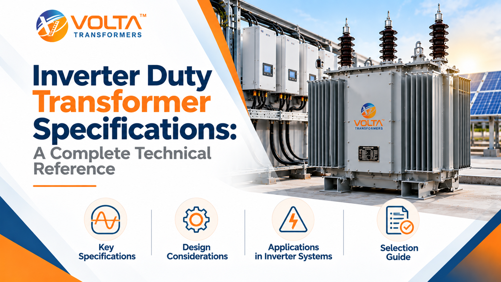
Connecting a solar or wind plant to the grid means stepping inverter output of a few hundred volts up to 11 kV or 33 kV. Choosing an inverter duty transformer for that job takes more than matching a kVA or MVA rating. Voltage compatibility, harmonic loading, insulation, thermal performance and grid integration all matter. Together, they decide whether the unit runs cool and compliant or overheats and draws utility objections.
This guide covers the inverter duty transformer specifications engineers should check, and how to verify them for a specific project. It is general technical information, so a qualified engineer should confirm the final specification.
What Is an Inverter Duty Transformer?
An inverter duty transformer is a power transformer built to take the AC output of power-electronic inverters. It steps that output up to a collection or grid voltage and provides galvanic isolation. People also call it a converter duty transformer. Typical uses include solar PV plants, wind installations and some industrial converter systems.
Unlike a conventional power transformer or distribution transformer, an inverter duty transformer must handle non-sinusoidal current. It must also cope with loading that follows irradiance or wind, and its winding and insulation arrangements must suit the inverter.
Why Inverter Duty Transformer Specifications Matter
Wrong specifications often show up later, as heat, losses or nuisance trips. The causes fall into three groups:
- Sizing errors: Undersizing overloads the unit and ages the insulation, whereas oversizing adds no-load loss and cost.
- Harmonic capability: Harmonic current adds eddy and stray losses, so it raises hot-spot temperature beyond the fundamental-frequency rating.
- Environmental protection: Dust, humidity, salt air, heat and altitude erode thermal and insulation margins.
In addition, a wrong voltage ratio, tap range or vector group creates compatibility problems that are usually found only at commissioning.
Key Inverter Duty Transformer Specifications Explained
Treat the table below as a list of parameters to check, not as universal values.
Specification | What it means | Why it matters | What to verify |
Rated capacity | kVA or MVA delivered continuously | Undersizing overheats; oversizing adds loss | Inverter output, loading profile, ambient, design basis |
Voltage ratings | Grid-side and inverter-side voltage | Mismatch affects inverter range and compliance | Inverter AC window, grid voltage, tolerance |
Frequency | Rated system frequency, 50 Hz in India | Sets core flux and losses | Match with grid and inverter |
Phases | Typically three-phase | Defines core and winding design | Winding count for plant layout |
Vector group | Winding connection and phase displacement | Affects neutral, earthing, circulating currents | Utility and inverter requirements |
Impedance | Percentage voltage drop at rated current | Sets fault current and regulation | Fault-level and protection studies |
Harmonic loading | Capability to carry non-sinusoidal current | Harmonics raise losses and hot spots | Inverter harmonic spectrum, loss method |
Insulation | Power-frequency and impulse withstand | Protects against overvoltage | Levels per standard, site coordination |
Cooling | Heat removal, such as ONAN (oil natural, air natural) | Sets thermal capacity | Whether natural cooling suits loading and ambient |
Temperature rise | Oil and winding rise over ambient | Governs insulation life | Limits at site ambient, altitude, loading |
Tap changer | OCTC (off-circuit) or OLTC (on-load) | Allows voltage adjustment | Range, steps, grid voltage variation |
Losses | No-load and load losses | Drives lifecycle energy cost | Guaranteed values, evaluation basis |
Short-circuit withstand | Ability to survive external faults | Determines survival under faults | Fault level, clearing times, evidence |
Environment | Dust, moisture, corrosion, altitude, access | Drives enclosure and derating | Site conditions in the specification |
Protection and monitoring | Temperature, oil-level, pressure relief, relays | Early warning and protection | Provisions required by utility and rating |
Losses deserve extra attention because they run for the life of the plant. Our article on ways to reduce transformer losses in industrial plants explains the basics of no-load and load losses.
Understanding Harmonics in an Inverter Duty Transformer
Inverters switch semiconductors at high frequency, so output current carries harmonic components even after filtering. Three effects are often confused:
- Harmonic current is the non-fundamental current itself.
- Voltage distortion is the resulting waveform distortion at the connection point.
- Transformer heating is the extra loss in windings and structural parts.
The impact depends on the harmonic spectrum, loading profile, winding arrangement and inverter characteristics. For this reason, assess it for the actual application instead of assuming it from a transformer’s name. IEEE C57.110 is a common reference.
A harmonic isolation transformer is one configured to help manage harmonic-related coupling or distortion between systems, depending on its design. However, it does not eliminate harmonics. Where limits apply at the point of common coupling, a harmonic isolation transformer is only one part of the answer, alongside filtering and system design.
Output Transformer vs. Drive Isolation Transformer vs. Inverter Duty Transformer
An output transformer sits after a converter or drive to match voltage or isolate the load. A drive isolation transformer, by contrast, sits ahead of a variable-speed drive. These are application-dependent roles, so neither is an automatic substitute for the unit used in renewable plants.
Aspect | Output role | Drive isolation role | Solar/wind inverter role |
Purpose | Matches voltage or isolates after a converter | Isolates and matches supply to a drive | Steps inverter AC up to grid voltage |
Applications | Drive outputs, motor or load matching | Industrial variable-speed drives | PV plants, wind farms |
Design focus | Converter waveform, cable effects | Drive harmonics, fault-current limiting | Grid voltage, loading profile, fault coordination |
Harmonics and insulation | Withstand fast-switching voltage stress | Carry drive harmonic current | Harmonic loading, dielectric design for grid voltage |
Selection factors | Converter data, load | Drive rating, supply fault level | Inverter data, grid code, site |
In short, a drive isolation transformer designed for a factory is not automatically suitable for a solar or wind plant.
Applicable Standards and Compliance
In India, power transformers are commonly specified to the IS 2026 series. The IEC 60076 series is used internationally and is often referenced in tenders. In addition, IEC 60076-16 covers wind turbine transformers, and IEC 61378-1 covers industrial convertor transformers, where applicable.
Before ordering, confirm the following:
- The standard and its edition
- Rated voltage and insulation level
- Temperature-rise limits
- Routine and type tests
- Short-circuit withstand expectations
- Utility or grid-code requirements
Manufacturer test reports and certificates show compliance, not model names.
How to Select an Inverter Duty Transformer for a Solar or Wind Plant
- Establish the inverter output, voltage window and loading pattern.
- Confirm the voltage ratio and grid interconnection requirements.
- Calculate capacity on the project design basis.
- Obtain harmonic data, then assess the added losses and heating.
- Confirm the vector group, neutral and earthing.
- Set impedance through fault-level coordination.
- Choose insulation, cooling and environmental provisions.
- Review losses, maintenance and lifecycle cost.
- Verify testing, documentation and compliance.
- Align the final specification with the inverter supplier, EPC contractor, utility and manufacturer.
Volta Transformers for Solar and Wind Applications
Volta Transformers, based in Gujarat, publishes this range for solar and wind plants: capacity from 100 kVA to 20 MVA; high voltage from 11 kV to 33 kV; low voltage of 380, 400, 415, 433, 440, 600 and 800 V, with customised classes available for both; ONAN cooling; and OCTC or OLTC tap changers. These are published ranges, not a guarantee of every configuration.
To review them, explore Volta Transformers’ inverter duty transformers for solar and wind plants. Then confirm voltage ratio, capacity, vector group, impedance and harmonic loading with the manufacturer.
Common Inverter Duty Transformer Specification Mistakes
- Sizing from inverter nameplate power alone
- Ignoring the harmonic spectrum and added losses
- Choosing an unsuitable vector group or earthing arrangement
- Overlooking ambient temperature, altitude and site conditions
- Treating impedance as secondary
- Assuming all units give identical isolation or harmonic performance
- Confirming testing, protection and utility requirements too late
- Comparing quotations without checking technical equivalence
Conclusion
Selecting an inverter duty transformer means matching it to a specific inverter, grid connection and site, not to a headline rating. Therefore, review capacity, voltage, vector group, impedance, harmonics, insulation, cooling and compliance together. Then verify them against current standards and inverter documentation, and consult the manufacturer before the specification is frozen.
Frequently Asked Questions
What is a converter duty transformer?
It steps solar or wind inverter output up to grid voltage, with isolation and a design suited to inverter loading.
What are the most important specifications?
Capacity, voltage ratios, vector group, impedance, harmonic loading, insulation, cooling, tap changer and losses.
How does it differ from a conventional transformer?
It is designed for non-sinusoidal current, variable loading and inverter-specific windings.
How do harmonics affect performance?
They add winding and stray losses and raise temperature; the effect depends on spectrum and loading.
Which cooling method is used?
Oil-immersed units commonly use ONAN; larger or hotter sites may need another arrangement.
How do I calculate required capacity?
Start from inverter apparent power at the connection point, then apply the project design basis and harmonic losses.
Can it serve both solar and wind plants?
Often yes, but wind projects can add requirements, so confirm per project.
How does it differ from a transformer used for motor drives?
A motor-drive isolation unit supplies a drive in a plant; this type connects inverter-based generation to the grid.

Leave a Comment