

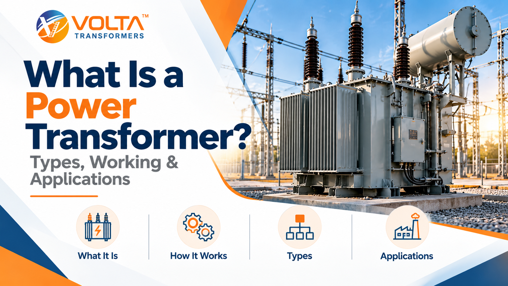
Power stations rarely generate electricity at the voltage that transmission lines use, and homes and factories rarely use it at the voltage those lines carry. Power transformers make those changes possible. A power transformer is a static electrical device that transfers energy between circuits through electromagnetic induction, raising or lowering AC voltage while keeping the frequency unchanged.
For a given amount of power, a higher voltage means a lower current, and a lower current means far less energy lost as heat in the conductors. As a result, utilities step voltage up for long-distance transmission and then step it down in stages for factories, offices and homes. This guide from Volta Transformers explains how power transformers work, what they’re made of, the main types, where they’re used, and how to choose and maintain one.
Power Transformer Definition and Role in the Grid
A power transformer changes the voltage of an alternating current supply without changing its frequency. Energy passes between the windings through a shared magnetic field, so there are no moving parts.
These machines sit at key points in a network. Near power stations, they raise generator output for transmission. In transmission substations, they connect networks that run at different voltages. Closer to the load, they lower the voltage for regional distribution and large industrial users.
However, a transformer doesn’t generate energy. Generators convert mechanical energy into electricity, whereas a transformer only converts one voltage and current level into another, losing a small share as heat. Because power transformers carry so much power, the network around them feels it when one fails.
How Does a Power Transformer Work?
The power transformer working principle is electromagnetic induction. A changing magnetic flux through a coil induces a voltage in it, and a transformer applies this idea with two windings on a common magnetic core:
- AC voltage applied to the primary winding drives a current.
- That current creates an alternating magnetic flux in the core.
- The core then carries the flux through the secondary winding.
- Finally, the changing flux induces a voltage in the secondary, which supplies the load.
For an ideal transformer, the turns ratio sets the voltage ratio:
Vp / Vs = Np / Ns = Is / Ip
In this equation, V is voltage, N is the number of turns and I is current, with p for primary and s for secondary. More secondary turns give a higher voltage and a lower current (step-up). By contrast, fewer secondary turns give a lower voltage and a higher current (step-down).
Throughout this process, the frequency stays the same on both sides. In addition, the process needs a changing flux, so transformers work on AC but not on steady DC.
Real transformers, however, aren’t ideal. Winding resistance, core magnetisation and stray flux cause losses that appear as heat, which the cooling system must remove. The insulation must also withstand the voltage between windings and to earth. For this reason, insulation quality largely decides service life.
Main Components of a Power Transformer
Components vary by design. However, most units include:
- Magnetic core: Laminated electrical steel guides the flux and limits eddy-current losses.
- Windings: Insulated copper or aluminium conductors. The primary receives energy, and the secondary delivers it.
- Insulation system: Paper, pressboard and insulating liquid or solid materials separate the live parts.
- Tank: This holds the active part and, in liquid-filled units, the insulating liquid.
- Tap changer: An off-circuit tap changer (OCTC) or on-load tap changer (OLTC) adjusts the voltage ratio to keep the output voltage within limits.
- Conservator and breather: In conventional oil-immersed units, an expansion tank and a silica gel breather handle oil expansion as the temperature changes.
- Cooling system: Radiators, fans, pumps or natural air circulation remove heat.
- Bushings: Insulated terminals bring the connections through the tank wall.
- Protection and monitoring devices: Temperature indicators, pressure relief devices and gas-detection relays, such as the Buchholz relay, flag abnormal conditions.
What Are the Different Types of Power Transformers?
Engineers group the types of power transformer by function (step-up or step-down), by insulation and cooling (oil-immersed or dry-type), and by phase (single-phase or three-phase). These categories also overlap. For example, a generator step-up unit is commonly a three-phase, oil-immersed, step-up transformer.
Type | Primary function | Common applications |
Step-up | Raises voltage | Generating stations, power plant grid connections |
Step-down | Lowers voltage | Receiving substations, industrial supply points |
Generator step-up (GSU) | Raises generator output to transmission voltage | Thermal, hydro and large renewable plants |
Auto-transformer | Shares part of one winding between primary and secondary | Interconnecting transmission networks at different voltages |
Oil-immersed | Uses insulating oil for insulation and cooling | Outdoor substations, high-voltage and high-capacity duty |
Dry-type | Uses solid insulation and air cooling | Indoor sites, buildings, fire-sensitive locations |
Single-phase | Transforms one phase | Smaller loads, or banks of three for large duty |
Three-phase | Transforms all phases in one unit | Most transmission and industrial networks |
Oil-immersed units usually handle higher voltages and capacities more readily, so the choice often follows the site and rating. For a closer look at that choice, see our guide to dry type vs oil-filled transformers. Similarly, our article on step-down transformer applications covers where step-down units fit.
What Are Large Power Transformers?
Large power transformers are high-capacity units that move bulk power through the backbone of a network. They also use the same power transformer working principle as smaller units. At their ratings, however, design, transport and installation become major engineering tasks. Standards and utilities also define “large” differently, so no single capacity cut-off applies.
Large power transformers connect generators to the grid at power plants, tie together transmission systems at substations, and supply energy-intensive industries. Key considerations include:
- Design: Engineers manage heat, fault forces and insulation stress for the specific site and duty.
- Transport: Road, rail and port limits may require shipping with some parts removed.
- Installation: Foundations, oil containment, fire protection and crane access need early planning.
- Cooling: High ratings may need forced air or forced oil.
- Maintenance: Repair or replacement can take a long time, so condition monitoring matters.
Applications of Power Transformers
Power transformers appear wherever voltage changes between source and user. Their requirements differ, however, because voltage, load pattern and environment differ.
- Power stations: Generator step-up transformers raise output voltage for transmission and often run near full load for long periods.
- Grid substations: They connect networks at different voltages, with loads that change by hour and season.
- Industrial facilities: Heavy motors and furnaces need a dependable supply stepped down from high voltage.
- Renewable energy: Solar and wind plants step output up to grid voltage, and variable generation affects loading and losses. Inverter-based plants often need inverter duty transformers designed for that duty.
- Commercial and infrastructure projects: Airports, data centres, hospitals and metros need a stable supply, and indoor siting often favours dry-type designs.
In other words, a generator step-up unit, a grid substation transformer and a factory supply unit all work the same way, yet engineers specify each one differently.
Factors to Consider When Choosing a Power Transformer
- Rated power and load: First, size for the real load profile, including peaks.
- Voltages: Match the primary and secondary voltages, regulation and tap-changing needs.
- Environment: Consider indoor or outdoor siting, altitude, humidity, dust and pollution.
- Cooling and ambient temperature: Confirm the cooling suits the hottest expected conditions.
- Efficiency and losses: No-load losses run constantly, while load losses rise with demand. Our article on ways to reduce transformer losses in industrial plants covers practical steps.
- Insulation and safety: Consider fire-safety rules, oil containment and the applicable standards.
- Maintenance and lifecycle cost: Weigh access, spares and service support, not just the purchase price.
- Future capacity: Finally, plan early for load growth.
Then write these requirements into a specification, and check the proposed design against the standards your project follows.
Power Transformer Maintenance and Safety
Routine inspection and condition monitoring keep power transformers reliable. After all, catching a fault early costs far less than dealing with an outage. Keep records, too, because trends in temperature and gas levels tell you more than a single reading.
- Insulating liquid: In oil-immersed units, periodic tests assess moisture, dissolved gases and general condition.
- Temperature: Similarly, winding and liquid readings show whether the unit stays within its design limits.
- Connections and bushings: Check for looseness, overheating, cracks and contamination.
- Cooling and ventilation: Keep fans, radiators and air paths clear and working.
- Protection systems: Test relays, alarms and pressure relief devices on schedule.
Above all, follow the manufacturer’s guidance and your site’s electrical safety procedures. Only qualified personnel should isolate, earth and work on this equipment.
Why Consider Volta Transformers for Power Transformers?
Volta Transformers manufactures power transformers from 1 MVA to 25 MVA, with voltage classes up to 69 kV and customised classes available on request. Cooling options include ONAN, ONAF, OFAF, ONWF and OFWF, and the range offers both OCTC and OLTC tap changers. The right configuration depends on your project’s voltage, capacity, operating environment and technical specification.
Conclusion
Power transformers raise and lower AC voltage through electromagnetic induction, without changing frequency or creating energy. Engineers classify them by function, insulation and cooling, and phase, and they serve power stations, substations, industry, renewables and infrastructure. So, when you choose one, start with rated power, voltages and load. Then test the choice against site conditions, safety rules, losses and long-term maintenance.
Frequently Asked Questions
What is the main purpose of a power transformer?
It changes AC voltage between parts of a power system, raising it for efficient transmission and lowering it for distribution and use.
What is the power transformer working principle?
It works by electromagnetic induction. Current in the primary winding creates a changing flux in the core, which then induces a voltage in the secondary. The turns ratio sets the voltage ratio.
What are the different types of power transformers?
The main types are step-up and step-down, generator step-up and auto-transformers, oil-immersed and dry-type, and single-phase and three-phase. One unit can also belong to several groups.
Where are power transformers commonly used?
They’re common at power stations, grid substations, industrial plants, renewable energy projects, and large commercial and infrastructure facilities.
What is a large power transformer used for?
It carries bulk power: connecting power plants to the grid, linking transmission systems, and supplying very large industrial loads.
What is the difference between a power transformer and a distribution transformer?
A power transformer generally works at higher voltages and ratings in generation and transmission. By contrast, a distribution transformer sits near consumers at lower voltages and ratings, usually with more varied loads. No single figure separates them.
Is a power transformer used in solar power plants?
Yes. It raises the plant’s output voltage so the plant can connect to the grid.
How can you improve power transformer efficiency?
Use low-loss core materials, a design matched to the real load, adequate cooling, sound connections and regular maintenance.

Leave a Comment